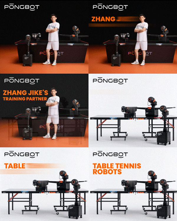
In this post we'll treat the subject of positioning the Nova at pos9 (likewise pos7), i.e. how i do it consistently.
Positioning the Nova at pos9 (and pos7)
I'd wish the company would release a stencil-like jig, i.e. a flat
rotary quadratic platform that can be easily aligned right at/in the corner of the table and on which the Nova is placed, to standardize the exact location of the robot in alignment no pun intended with the app. It would then be easy to physically rotate the robot's orientation, read out its angle, and enter that number into the app when setting up a Custom Drill. Without such a well-defined exact location of the robot within the ninth sudoku cell, how could the visualization in the app possibly be accurate?
Anyway, first we need to be able to reproduce an exact location (
x-, y- coordinates) and exact angle of orientation (
° degrees) of the Nova on the table, in a fast and easy manner. From my testing of the Programmed Drills, a perfect choice of orientation be
+15.0° (or likewise -15.0° for pos7), not 21°. We'll leave the robot at this orientation for all Programmed Drills and Custom Drills initiated from pos9.
Step 1. Position the two rubber feet of the Nova's rear section as closely to the table's edge as possible. With your finger you should be able to touch/feel the alignment of rubber and edge:
Feel free to mark that touching point with a piece of tape:
Same with the other rubber:
Here a more frontal view of the tape:
The 2 tape snippets are not sufficient IRL to accurately set the 15°.
Step 2. With a cheap thin carpenter's
framing L shape square, held against two rubber feet, you can see the angle of orientation forming at the table's edge. For convenience, i shifted the framing square such that its "100"-mark was right at the tip of the 'triangle in the picture':
Convenient because now you know where to place the triangle ruler. And bull's eye, the measured angle reads indeed 15°:
Since the correct angle has been confirmed, you can put the triangle ruler away, and draw a fat green line along the framing square (with a dry erase marker):
If you have the framing square handy, you'll be able to reproduce the exact position and orientation of the Nova in the ninth sudoku cell simply with the help of the framing square and the two green lines, while the two red tape snippets are just for quick rough reference to get you started:

For pos7 it's likewise. Once you have drawn the two fat green lines for pos7, it's super quick'n fun to place the Nova exactly there. Just place the robot on the table somewhere near the table corner, slide the L shape framing square "underneath" the robot, touching three 🧐 rubber feet simultaneously, then slide/shift the robot towards the corner such that the framing square perfectly aligns with the two fat green lines. First with the one green line, then with the other green line. And if you want, you could leave the framing square the whole session time there (so i finally found an IRL sensible purpose for the ultracheap 5.99€ China-made framing square which i had bought over 2 years ago hooray!):
Step 3. In the app, you can set the angle to "set angle =
+15°", as one normally/logically would do. If you do so, you'll notice that the visualizations (ball flight trajectories) are quite a bit off!

That's understandable because the app doesn't know where exactly you positioned the Nova within the ninth sudoku cell. By experimenting with different set angles, you'll learn that, for app visualization purposes, using the "set angle =
+9°" setting is more suitable. So if you want the app visualizations to be a better matching predictor of the ball trajectories, you should go with that set angle instead of +15°, even though IRL the actual angle
is +15° as proven by the photos. Then, when you work with Custom Drills, simply ignore the +9° info bit ("virtual discrepancy") in the drill settings.
Comment:
In practice, one can/could ignore the app visualizations altogether! In the end, what really counts is that the robot produces balls from the above exactly defined pos9 which have the properties and quality as desired. And that depends only on the ball settings of the drill, not on the set angle (app info bit) of the robot. And certainly not on the app visualizations! The manual even states that "
3.5.5. Real-time Animation (…) This animation effect is for reference only. ( Figure 3-16 )". However i find the app visualizations immensely useful, since the ball consistency is pretty good and the trajectory predictions are pretty good too. In fact, imho the app visualizations are the strongest point of the app, so i wouldn't want to do without them!
The choice of 15° instead of 21° for the IRL angle enables us to use the Programmed Drills from pos9 without editing/modification/calibration: all balls land on the table under nice sector coverage. Understandably there's an exception: the wide long-line underspin balls, i.e. the "Loop(B)" from pos9 (or likewise the "Loop(F)" from pos7), would sometimes fly too long ("out!"); for a particular difficulty level (⭐, ⭐⭐, or ⭐⭐⭐), feel free to
Calibrate the starred drill, setting the flight path
Shorter By 5 (out of 10) increments. Not all three difficulty levels of a potentially affected Programmed Drill would need this calibration adjustment; the calibration is saved separately for each difficulty level of each Programmed Drill, so better use it only when really needed. Note that the calibration setting remains saved, even when you switch the robot position to pos7 or pos8 or etc.